
Projects and Bus Configuration
Modules
| Module | Purpose | Resource relationship |
|---|---|---|
| CAN | Classic CAN/FD, DBC decoding and simulation | Shares its interface with Uart2CAN |
| LIN | Master scheduling, slave capture/responses, LDF decoding | Shares its interface with Uart2LIN |
| UART | Serial data forwarding | Dedicated UART interface |
| Uart2CAN | UART utility mode on the CAN bridge | Excludes CAN |
| Uart2LIN | UART utility mode on the LIN bridge | Excludes LIN |
| Python | MCU Python REPL | Exclusive during measurement |
Uart2CAN/Uart2LIN do not automatically convert arbitrary serial bytes into protocol frames. Remove the original module before adding another using the same interface; disabling it does not remove the configuration conflict.
When Python is enabled, Start opens only Python. Disable or remove it before using ordinary CAN/LIN/UART measurement. A combined CAN + LIN + UART project is supported.
Network configuration
Configure hardware while stopped. Attach a DBC or LDF if needed, open Bus Configuration, and use the tree and diagram to select modules, database nodes, loggers, and replays.
Tree expansion states are saved with each project and restored when reopening it. Other projects keep their own states.
Enabling a node's simulation causes the tool to send or respond on its behalf. Leave simulation off when observing real ECUs. CAN simulation sends messages with defined cycle times, except those unchecked under Active in the node panel. LIN slave simulation configures responses.
The current LDF master implementation sums table delays into a repeat cycle for its entries; it does not guarantee the original sequential timing. The LIN Schedule window switches between Custom and LDF: LDF enables LDF master simulation for the table picked there and stops periodic custom rows; switching back to Custom stops the LDF schedule. An LDF slot unchecked under Active is not sent, but its delay still counts toward the cycle.
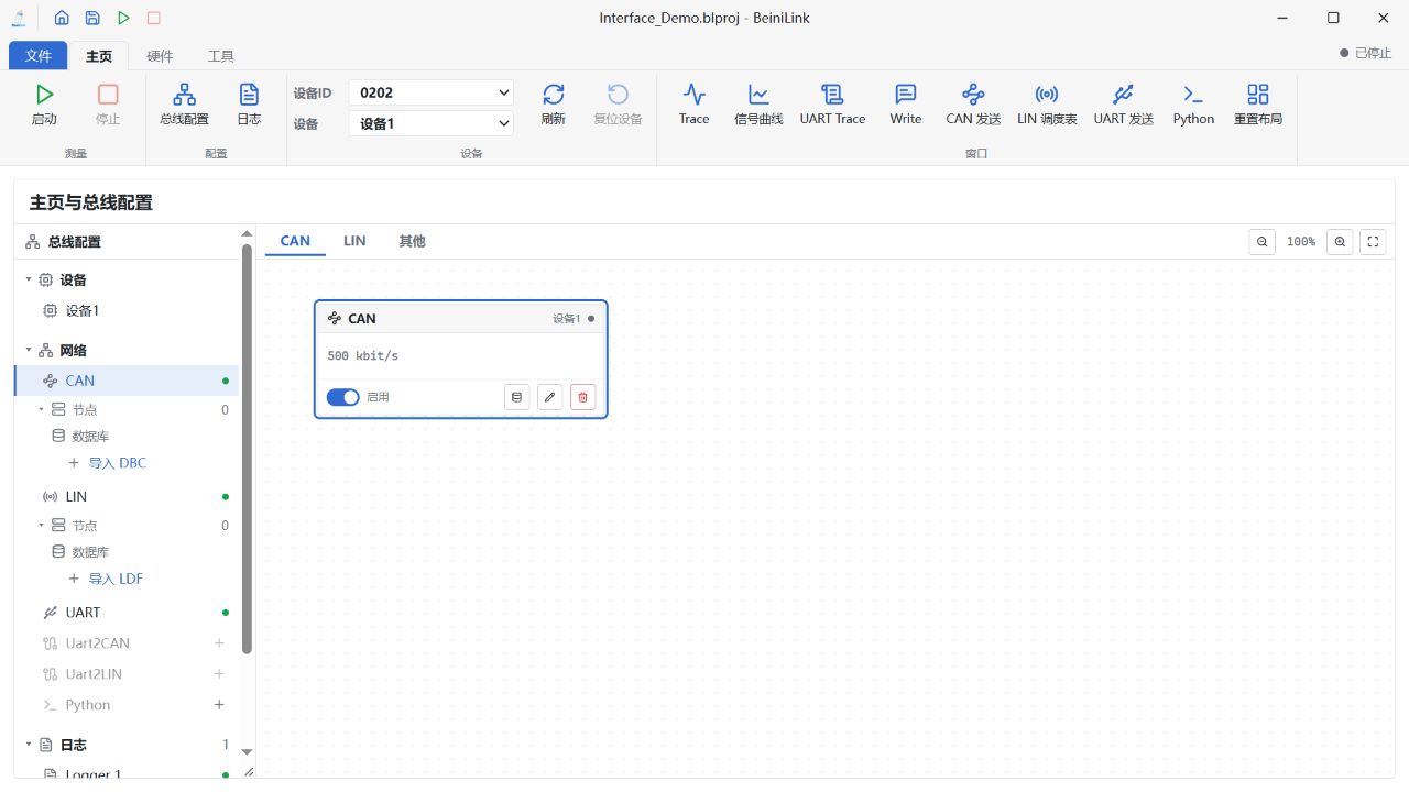
The bus configuration tree is on the left; device, bus and Logger nodes are on the right. Chinese UI, example configuration.
Windows
Open Information through Home and other panels through View. Right-click a title or tab to choose Docked, Floating, or Separate window. Drag docked tabs to another group's center to merge them, or to its edges to split the layout. Floating windows move and resize within the main workspace.
A separate window can return using Return to main window or the title context menu. Group operations can affect all merged tabs. Save the project to retain its layout, or reset the layout through View.
Closing a panel does not stop measurement. Reopen Information from Home and other panels from View; use Stop to end measurement.