
LIN Master and Slave
Configuration
Select 2400, 9600, 10417, 19200, or 20000 baud and the master/slave role. Connect LIN and reference ground and verify network power. Attach an LDF for names, lengths, publishers, and checksum definitions.
Current firmware enables 12V at startup; older builds may differ. The 12V on/off controls in Hardware → Power operate an independent output; the command goes through the LIN channel, so open LIN first. Opening or closing LIN does not change it automatically.
Master transmission
For a complete frame, select Header + response, enter ID 3C, bytes 01 02 03 04 05 06 07 08, classic checksum, and Manual trigger. Start and send.
Enter six-bit hexadecimal IDs 00–3F, not protected PIDs. Payloads have 1–8 bytes. Diagnostic IDs 3C and 3D use classic checksum; match other frames to the network definition.
For Header only, the data field is the expected response length, such as 8. A successful header appears as REQUEST with empty data even without a response. Look for RX separately. !3 means LIN timeout, not proof that no header was sent.
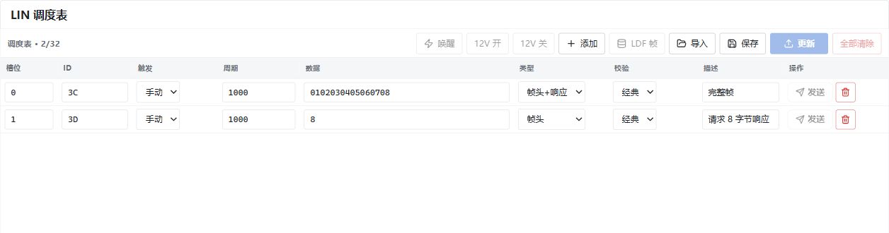
Master example: 3C sends a complete frame; 3D requests an eight-byte response. Both use manual triggers. Chinese UI.
Conditional LDF frames
Event-triggered frames preserve associations and collision tables. Silence leaves an empty header; an invalid response runs the resolution table once before returning. Sporadic slots send the first updated associated frame, otherwise remain idle. Initial configuration does not mark data updated; editing and applying a signal/payload does.
Limits: 64 frames, 16 groups, 16 members per group, 16 tables, 32 entries per table, 128 entries total. Slot delays are integer milliseconds. Disabled entries retain their time slot; required collision members cannot be disabled.
Scheduling
Up to 32 rows, with periods of 1–65535 ms. A periodic row's send action starts or stops that row; Update programs the MCU and activates periodic rows. Clear all clears the device schedule without deleting displayed project rows. Saving files does not apply edited values to the device.
Slave capture and responses
Select Slave while stopped. Keep the response table empty and node simulation off for capture only. To answer an ID, add its payload and checksum, then start. Opening applies the table; Update reapplies edits, and deleting an applied row removes its response.
For example, configure ID 21 with eight bytes and enhanced checksum, then have an external master send its header. Unconfigured IDs are observed without responses. Up to 64 response entries are supported; avoid duplicates.
Slave mode does not originate headers or master wakeup operations. LDF node simulation uses the same response resources, so avoid conflicts with manual responses. Master Wakeup is a bus wakeup, not an MCU reset.